SolvisMax – The Pinnacle of Heating and Comfort
Elegance. Efficiency. Effortless Control.
Experience next-level comfort with the SolvisMax system — a seamless, all-in-one solution for hot water and hydronic heating. Designed to integrate effortlessly with your home or commercial project, SolvisMax combines cutting-edge technology, sustainable energy, and intuitive control to create the ultimate living environment.
The SolvisMax Advantage:
All-in-One Luxury: Hot water, floor heating, radiators, towel rails — even pools — elegantly powered by a single, intelligent system.
Effortless Comfort: Hydronic heating delivers quiet, consistent warmth with complete control over your environment.
Smart & Connected: Monitor and manage your system remotely via smartphone or browser — anywhere, anytime.
Sustainable & Cost-Efficient: Integrate solar technology for energy savings and access government rebates and STCs.
Future-Ready & Modular: Expand or upgrade your system without replacing components, ensuring your investment grows with your needs.
Reliable & Worry-Free: Industry-leading warranties and professional support give you total peace of mind.
From bespoke homes to sophisticated commercial spaces, SolvisMax transforms energy into comfort, style, and sustainability.
Invest in SolvisMax — where intelligent design meets luxurious living.
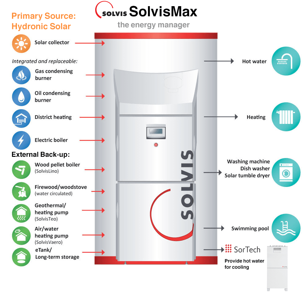
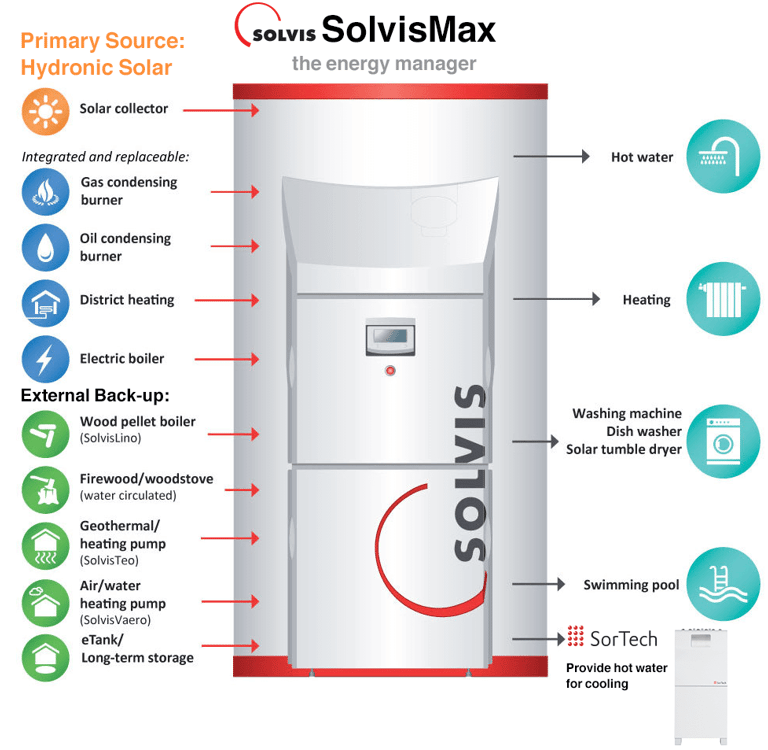
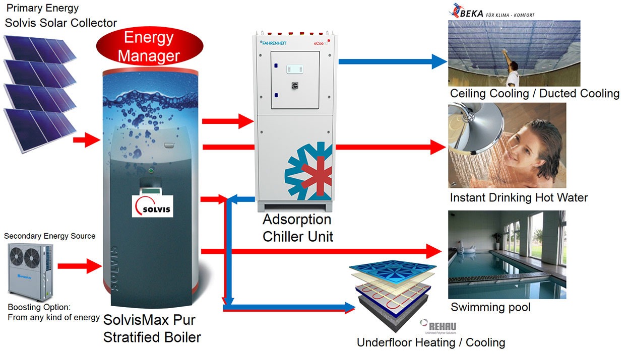
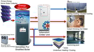
Use a modular solar hydronic heating system in conjunction with a Fahrenheit adsorption chiller to get free cooling.
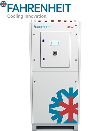
The Fahrenheit Chiller is really a World Wonder – you input Hot Water and Cool Water comes out!
This cooling process is totally mechanical and does not rely on electricity to make cool water. Now this is a very big step in sustainable energy, as a combined Solar Hydronic system with a Fahrenheit Chiller results in FREE Heating & Cooling in most Australian regions!
Thanks to Fahrenheit German engineering, it is only a low energy input of 50°C – 95°C water temperature to get achieve an output of 8 – 21°C chilled water!
The low solar harvesting temperature even on cloudy days from a SOLVIS Solar System in its high flow rate, is enough to supply not only residential homes but even Commercial / Industrial projects up to 240kW!
Quick Example:
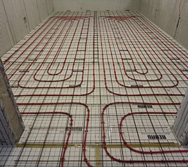
For an Australian residential house of 650m2 with sufficient insulation barriers in place, the whole house could be cooled with chilled water between 10-14°C through underfloor pipes or ceiling cooling pipes.
This process would result in a constant and comfortable room temperature, in South Australia if the outside temperature was 42°C and the same cooling input as above, the room temperature can be held at a constant < 22°C.


Discover the potential
Drastic Energy Saving
Only running on ~50°C hot water as its energy source, Fahrenheit Chillers require little input energy to achieve large scale cooling capacities.
Expandable Interconnection
Fahrenheit Chillers can be interconnected which will result in a higher cooling capacity of up to 240kW or a greater heating output of up to 800kW respectively.
Heatpump Operation
A supporting heatpump operation mode can be selected with Fahrenheit Chillers to benefit heating requirements.

How it works
The mechanics of a module consist of the following 4 phases:
Phase 1: Desorption / Adsorption
The desorber is flooded with hot water (hot-water circuit). As a result the cooling agent, which has accumulated on the inner surface of the silica gel, is being expelled and liquefied on the condensator. The heat that is being generated during the liquefaction is being discharged through the re-cooler.
At the same time, the adsorber adsorbs the water vapor that is being created inside the evaporator when the object to be cooled takes in the heat supplied through the cold-water circuit. The heat that is being created during the adsorption process will be discharged – together with the liquefaction heat – into the environment. Operational phase 1 will run until the required cold-water temperature set point has been reached.
Phase 2: Heat Reclamation
Immediately after phase 1 the 3-way valves in the flow section of the three circuits will be set such that the previously desorbed Adsorber 1 will now be flooded with re-cooling water. The energy, which initially was stored in the desorber, will not be simultaneously claimed at the mean temperature sink; but instead will be pumped in the driving circuit over a period of time.
The return of Adsorber 2, which will be desorbed following the adsorption process, will for a set time supply the re-cooling circuit. Only after a certain temperature difference between the two adsorber returns has been reached, will phase 2 be terminated by switching of the 3-way-valves in the return section of the three circuits.
Phase 3: Desorption I Adsorption
The desorber will be flooded with hot water (drive temperature) and simultaneously adsorbed. The process of adsorption/desorption takes place analogously to phase 1.
Phase 4: Heat Reclamation
Immediately after phase 3 the 3-way-valves will switch in a manner such that the previously desorbed Adsorber 2 will now be flooded with re-cooling water. The heat reclamation process takes place analogously to phase 2.
Operational Setup
From an operational point of view, the Adsorption Chiller Aggregates consists of the following three cycles:
(1) Hot-Water Circuit
By means of the hot-water circuit (driving circuit), thermal energy is being supplied to power the Adsorption Chiller Aggregates and the heat exchange that happens inside of it.
(2) Re-cooling Circuit
The heat that has been supplied to the Adsorption Chiller Aggregates (heat from the object about to be cooled and heat to dry the equipment) will be removed through the re-cooler by redistribution to the environment at mean temperature level.
(3) Cold-Water Circuit
Utilising the cold-water circuit, heat will be removed from the object about to be cooled.
Technical Information
Please download the PDFs below for more information about this product.